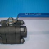
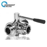
Ball valve temperature and pressure limits:
The nameplate on the valve shows the maximum operating pressure allowed by the ball valve at the maximum and minimum operating temperatures.
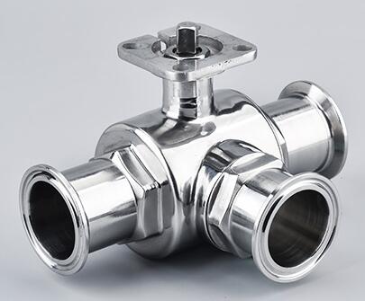
Seats and seals made of PTFE or RTFE shall be operated at temperatures ranging from – 290 C to 2000 C. The operating temperature of other types of seats and seals shall be checked by the factory.
The nominal pressure level of the pneumatic ball valve indicates the maximum working pressure of the valve at normal temperature. For example, PN4.0 indicates that the maximum operating pressure is 40Bar (4.0MPa) at the operating temperature of -290 ~380 C.
Electric or pneumatic actuators can be found in the corresponding instructions.
Installation of ball valves:
(1) Remove the protective caps at both ends of the flange, fully open the ball valve, and clean the valve and pipeline.
(2) Before installation, the whole machine should be tested according to the specified signal (to prevent the vibration caused by transportation from affecting the service performance).
(3) Should be taken not to use the actuator as a lifting point to avoid deformation or damage to the actuator and its accessories.
(4)It should be installed in horizontal or vertical pipelines.
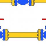
(5) There should be no droop or external force near the installation point. Support or support can be used to eliminate deviation and bending of the pipeline.
After fixing the position of the valve, the bolt and nut must be cross-locked with the torque after the anastomosis according to the regulations.
Operation and use of valves:
1. Make sure that the pipeline and valves have been flushed before the operation.
2. The operation of the valve is driven by the input signal of the actuator to complete the rotation of the valve stem: when the valve rotates 1/4 times in the positive direction, the valve closes; when the valve rotates 1/4 times in the reverse direction, the valve opens.
3. When the direction of the actuator indicates that the arrow is parallel to the pipeline, the valve is in the open state; when the direction of the arrow is perpendicular to the pipeline, the valve is in the closed state.
Maintenance of ball valves:
With a longer service life and maintenance-free period, it will depend on the following factors: normal working conditions, maintaining a harmonious temperature/pressure ratio, and reasonable corrosion data.
Be careful:
The pressure fluid still exists inside the valve body when the ball valve is closed.
Remove pipeline pressure and keep the sanitary valve in an open position before repair.
Before maintenance, disconnect the power or gas source
Separate the actuator from the bracket before maintenance
1. The packing must be locked again.
If microleakage occurs at the filler, the stem nut must be locked again.
Note: Do not lock too tightly, usually lock 1/4 to 1 turn again, and the leak will stop.
2. Replacement of Seats and Seals
A), Dismantling
The ball valve maintenance valve is in the half-open position, flushing and clearing the dangerous substances that may exist inside and outside the valve body. Close the sanitary ball valve, remove the connecting bolts and nuts on both flanges, and then remove the valve completely from the pipeline. Dismantle the driving device in sequence, actuator, connecting bracket, anti-loosening washer, stem nut, butterfly spring, wear-resistant plate, stem packing. Remove the cover connecting bolts and nuts, separate the cover from the body, and remove the cover washer. Confirm that the ball is in the “off” position, which makes it easier to remove it from the valve body and then from the seat. The stem is pushed downward from the hole in the body until it is completely removed, and then the O-ring and the packing under the stem are removed.
Note: Please operate cautiously to avoid scratching the stem surface and the sealing part of the body packing box.
B) Reassembly
Clean and inspect the parts and remove them. It is strongly recommended to replace the seats and cover gaskets of spare parts packages. Assemble in reverse order of disassembly. Cross-lock flange bolts with specified torque. Lock the stem nut with specified torque. After the actuator is installed, the corresponding signal is input to drive the spool to rotate through the rotating stem to make the valve open and close.
