The relief valve is installed between the supply and return of a heating system, in systems without mixing valve; it can also be installed between the pressure and suction side parallel to the heating circulation pump.
The valve limits the delivery pressure of conventional circulation pumps. It ensures a minimum volume flow in the boiler circuit by opening as soon as the delivery pressure exceeds the value set on the valve. This case occurs when little or no heating power is required in the connected heating circuit. In addition, the relief valve reduces the sometimes annoying throttle noises of thermostatic valves and possible vapor bubble formation and thus cavitation damage to the impeller. However, in comparison with speed or even pressure-controlled pumps, no energy saving can be achieved with a relief valve, since the pump continues to deliver a constant volume flow.
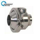
The sanitary relief valve is widely used in industry to protect the user and system components by avoiding overpressure. To function properly, the relief valve must be mounted in connection with the operating pressure. The relief valve is symbolized in a circuit diagram by a normally closed boom and a spring. The arrow indicates that the spring can be tared by the user.